 HVAC ResLoad-J Online Help
The HVAC ResLoad-J app for the iPad will revolutionize your HVAC and HVACR business. This app allows you to perform ACCA-approved Manual J8-based HVAC cooling and heating load calculations.
Table of Contents
1. The App's Capabilities
2. Shortcut to Video Tutorials
3. Frequently Asked Questions
* Is HVAC ResLoad-J ACCA-approved?
a. What does red text mean?
b. How do I delete a project?
c. How do I restore defaults in a textbox (make it red again)?
4. HVAC ResLoad-J Cloud: Sync all your projects to the Cloud
5. Learn Basic iPad Commands for HVAC ResLoad-J
a. Getting Started and Getting Comfortable
b. The Interface Overview
c. Changes to the Interface in Landscape and Portrait Mode
d. Navigating and Key Commands Using Swipe Gestures - Learning the Swipes
i. Swiping to Navigate
ii. Adding Items and Swiping to Delete Items
e. Selecting an Item from the List Selector to Edit
f. Entering Project Data - Segments
g. Entering Project Data - Sliders
h. Entering Project Data-Text Boxes
i. Why is the Textbox Font Red? - and Restoring Defaults in Text Boxes
i. Entering Project Data - Window Launchers
j. Changing Project Orientation
k. Changing Defaults - Using the iButton
6. In-Depth Tutorial
a. Let's Start in Block Load Mode
i. Project Start-Entering basic information
ii. Project Start-Entering your weather information
ii. What does Changing the Calculation Method do?
iii. Learning about the Block Loads Breakdown
iv. Moving on - Learn about System General Inputs
v. System Description and System Type
vi. Total Floor Area - cooling vs. heating
vii. Explaining Average Room Height
viii. Number of Bedrooms and Occupants
ix. Appliance Load Basics
x. Moving to System General Inputs
xi. Defining your Room and Supply Air Conditions
xii. Heat Recovery SER
xiii. Moving on to System Additional Inputs
xiv. Defining Envelope Tightness
xv. Cooling Infiltration Method
a. Manual J Air Change Method
b. Blower Door Method
c. Direct Entry Method
xvi. Heating Infiltration Method
xvii. Furnace Burner Input
xviii. Blower Heat Gain
xix. Calc Vent Rate vs. Man Vent Rate
xx. Exhaust Airflow
xxi. Hot Water Piping
xxii. Duct Loads
xxiii. Winter Humdification
Defining Project Wall, Door, Window, and Skylights
xxiv. Example - Creating an Above Grade Wall
- Tips on Envelope Inputs for Above Grade Walls
- Tips on Defining a Door
- Tips on Defining a Below Grade Wall
- Tips on Defining a Partition Wall
- Tips on Defining a Ceiling(Roof)
- Tips on Defining a Partition Ceiling
- Tips on Defining a Floor
- Impact of Changes To Envelope on Load Calculations
xxv. Solar Load and AED Calculations
xxvi. Defining Windows
xxvii. Defining Internal Shades and Insect Screens
xxviii. Defining External Sunscreens
xxix. Defining Overhangs and Ground Reflectance
xxx. Defining Skylights
b. Understanding the difference between Block Load and Room-by-Room Load
i. Defining Rooms
ii. Defining Envelopes
iii. Defining Windows
iv. Defining Skylights
c. Projects with Multiple System Types
d. Warning Flags
e. Reports
i. System Reports
ii. System Reports Descriptions
iii. Emailing or Printing System Reports
iv. Room Reports
v. Email Reports
vi. Email Database
HVAC ResLoad-J Capabilities
Can:
- Altitude Correction Factors
- Block load calculations
- Block loads for single speed single zone systems
- Block loads for variable volume single zone systems
- Block loads for variable volume single zone systems
- Custom internal load entry
- Engineered ventilation systems with imbalanced flow rates
- Multiple systems within a single project
- NFRC-Rated glazing products
- October cooling load calculations
- Radiant floor heating systems
- Room by room load calculations
- Overrides of weather and altitude Defaults
- Overrides of envelope construction U-value and SHGC values
- You can sync all your projects to the cloud to backup and share projects
Cannot:
- Custom duct dystems (Tables 7 Only)
- Latent heat recovery
Shortcut to Video Tutorials
To take a look at a video tutorial of how to navigate the app, click here. When you are done with the app, go ahead and click here (what will these teach you?). (need links to these) But you can read about everything the videos show by staying with us and reading on.Frequently Asked Questions
Q. Is HVAC ResLoad-J ACCA-approved?
A. Yes.
Q. What does red text mean?
A. See here. for more information
Q. How do I delete a project?
A. See here.
Q. I deleted the default behavior in the text box, how do I restore it?
A. See here.
Quickstart Guide: Basic Commands for HVAC ResLoad-J
If you’ve never used an iPad before, or you just want to learn the basics of how to use HVAC ResLoad-J with just a little bit extra help, then this section is a great place to start. We also offer you a full tutorial below. Reading the next couple of paragraphs will clarify some basic commands that can help you become acquainted with how to use touch commands essential for using the app on the iPad, as well as learn some basics like how to start a project and other features not covered in the FAQs. This section is a little bit more involved than the FAQs but a little less than the whole tutorial. We like to think that a person who is curious and motivated can read this section and then test out the app on their own, without the tutorial, and learn about 80% of the app without any further instruction. The full tutorial goes deep and can answer all the questions that people may have about how to use the app. Even if you plan on doing the tutorial, this stuff is important...so, read on.
First thing to know, the app takes advantage of the fact that the iPad works in both Landscape Mode and Portrait Mode. Whichever way you rotate the iPad, the app will adjust its screen to accommodate you. We are assuming you have your app open. If not, go ahead and open it now. You should be able to twirl your iPad from portrait to landscape mode, and you should see the interface update to accommodate the different views.
|
|
|
| iPad in Portrait Mode | iPad in Landscape Mode |
On Screen Basics - Getting to Know the Interface
Take a look at the image below and get comfortable with the words we use to describe the interface. We will use these terms often: List Selector, Input Mode, Data Entry Window, Load Calc Mode, and User Support often throughout the help section, so be sure to get familiar with them.
|
|
| Overview of ResLoads iPad App Layout and Flow |
| List Selector – | Holds all of the objects that have been created. It won’t always read “Project List” like it does above. It will change depending on the project input mode you are in. To select an item, it is very simple. Just touch your finger onto the item in the list you wish to make active. The active item is always highlighted in blue, as can be seen above. |
| Input Mode – | Consists of a series of 4 segmented buttons next to one another. The one that is darkest….that is the mode you are in currently (currently we are in Project Mode). Changing the input mode is as simple as selecting another button. Not only will this change the values in the List Selector, but also what is shown in the Data Entry Window. The current mode selected will be a darker shade than the other buttons. |
| Data Entry Window – | A bulk of your time will be spent here, where the work is done to actually define the data that is in your project. The basic look of it will change, depending on your Project Input Mode. |
| Load Calc Mode – | There are two main types of load calculations in HVAC ResLoad-J, a Block Load (or whole building mode), and Room-by-Room Mode. The current mode selected will be a darker shade than the other button (we are currently in Block Load mode). |
| User Support – | This area is a place to go and print reports, launch HVAC ResLoad-J Help (where you are now), find more information, and launch the all-important calculate button when it is needed. |
Major Differences between Landscape and Portrait Mode
To see the difference between Landscape and Portrait Mode....if you haven't already...Let's start with the application open in Landscape Mode, like in the picture above. Now go ahead and rotate your app into portrait mode. You notice that there are a couple of changes, like the List Selector disappears. You will notice that there is a small button on the top left corner of the screen, which we have circled in the picture below. At the start of a project, your Input Mode will likely be Project Mode. If you are, this button will say "Project List", if you are in Envelope Mode, the Button will say Envelope List, if you are in Window/Door Mode, the button will day Window/Door List, and so on...Pressing this button will make a List Selector (ref link) pop up on the left. Now the list selector is active, and you can navigate it, select an item in the list, or add or delete items from the list.

|
| ResLoads HD App in Portrait Mode, with Input Mode = Project Mode |

|
| ResLoads HD App in Portrait Mode, with Input Mode = Project Mode and the List Selector Active |
Now you notice that your Data Entry Window is partly obscured by your List Selector that has popped out. This is fine if you want the List Selector, but what if you don't? While you are in Portrait Mode, just touch the screen anywhere off the List Selector and it will go away
Ok, now let's rotate back into landscape mode, and you will see the List Selector reappear on the left side of the screen. In the Landscape Mode, the List Selector is always there and can't disappear like in Portrait Mode.
Navigation and Key Commands Using Swipe Gestures - Learning the Swipes
Swiping is familiar to a lot of iPad users. Here are just a few pointers for learning how to swipe in the app. This should help you understand what to swipe, when to swipe, and how to make the most use of your fingers in HVAC ResLoad-J. We also teach you some tricks that will make the tutorial easier for you.
|
|
Swiping left is a basic command where you first start with your finger on the screen (indicated in the picture with the finger encircled), and then, without taking your finger off the screen, move your finger to the left in a smooth, fairly quick motion. The left swipe is used to navigate between input windows in the Data Entry Window. A swipe to the left will advance you in the project. In other words, a swipe left is a lot like turning the page in a magazine, it gets you closer to the end of your project. The swipe left and can also be used to Delete Items in the List Selector |
|
|
Swiping right is a basic command where you first start with your finger on the screen (indicated in the picture with the finger encircled), and then, without taking your finger off the screen, move your finger to the right in a smooth, fairly quick motion. Data Entry Window. A swipe to the right will take you backwards you in the project. In other words, a swipe left is a lot like turning the pages back in a magazine, it gets you closer to the start of your project. The swipe left and can also be used to Delete Items in the List Selector |
|
|
Swiping down is a basic command where you first start with your finger on the screen (indicated in the picture with the finger encircled), and then, without taking your finger off the screen, move your finger downwards in a smooth, fairly quick motion. A swipe down is a way to go to the top of the Data Entry Window, or the top of a List Selector. No matter whether you are in Landscape or Portrait Mode, it returns you to the top of the current page. You can use the swipe down to see things at the top of the screen that you couldn't see otherwise, because you've scrolled too far down on the page. |
|
|
Swiping up is a basic command where you first start with your finger on the screen (indicated in the picture with the finger encircled), and then, without taking your finger off the screen, move your finger upwards in a smooth, fairly quick motion. A swipe up is a way to go to the bottom of the Data Entry Window, or the bottom of a List Selector. No matter whether you are in Landscape or Portrait Mode, it brings you towards the bottom of the current page. You can use the swipe up to see things at the bottom of the screen that you couldn't see otherwise, because you've haven't scrolled down far enough on the page to see what might be below your field of view. |
There are a few tips for swiping. Remember, swipes are used only for two things in HVAC ResLoad-J...to navigate the Data Entry Window and to delete items from the List Selector. We'll be teaching you more about deleting in a section below. Here are some tips for navigating using swipes:
1. Don't start your swipe by placing your finger over text box,
or picker (which you will be introduced to below). If you are swiping on the
Data Entry Window
find a spot on the screen that is grey where there are no windows or places to enter data.
In the List Selector,
you only use up and down swipes to navigate. If you do have so many items in the list that you do need to navigate up and down on the
List Selector, use a quicker flick of your finger and don't spend too long with your finger on
the screen.
2. Think of the swipes to navigate a lot like using your finger to turn the page of a magazine, pretend like you are have licked your index finger and changing pages quickly with your index finger. Don't actually lick your finger though.
Now, we are going to move on to using left and right swipes to add and delete items from the list selector.
Making Basic Changes - Learning to Add and Delete Items
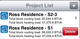
It was mentioned above that swipes are used to delete items in the List Selector. The iPad is pretty easy to use, but a lot of customers ask how to delete items from the List Selector, which is important in order to navigate the app. We will start by assuming that you are following along on your iPad and your Input Mode is Project, meaning all projects will show up in the list of your List Selector. Note that you cannot delete the Project named "_Default". You will need to have at least two projects in your Project List. If you only have the one labeled "_Default", you can quickly add an item to your project list, by clicking for instructions here, then return to try this delete command.
To delete an existing project, just make either a left swipe or a right swipe over the project you want to delete in the List Selector. The swipe is just a quick motion. We like to think of a swiping left or right to delete an item being like drawing a line with your finger quickly and smoothly over the screen. Another way to think about swiping is to pretend you are drawing a line with your finger through the item you are trying to delete. Below we are attempting to delete the Ross Residence - S1 with a swipe right.

|
| Swipe motion to delete an item from a list. In this case, we initiate deleting project from the project list |
When you do this, a red delete button will show up to the right of the name of the project.
|
| Swipe Motion will bring up the Delete Button in any List |
Hit the red button and it wil delete the project, without asking you any questions. So make sure you want to delete it before pressing that red button! If you choose to cancel the delete action prior to pressing delete, just press anywhere on the List Selector that is NOT NEAR the delete button, and the command is cancelled.
Adding an Item to a List
If you want to make a new item press the ![]() button on the top
right of the any list in the List Selector.
If your Input Mode is Project Mode, then after pressing the button a new project is created, if your
Input Mode is Envelope Mode, then pressing the
button on the top
right of the any list in the List Selector.
If your Input Mode is Project Mode, then after pressing the button a new project is created, if your
Input Mode is Envelope Mode, then pressing the  button
would make a new Envelope, etc.
button
would make a new Envelope, etc.
Choosing Your Active Item in the List Selector
The List Selector, as you have seen, may have one of several different items in it. The active item is always highlighted in blue. Changing the active item in the list is easy, just push your finger on the item you wish to make active. Once active, the item you've selected is editable in the Data Entry Window. If an item is not currently active item in the list (not highlighted blue) you cannot make any edits to it. An item does not have to be active in order to delete it.

|

|
| The current active item in this list of Window/Doors is Item A. Pressing your finger on item B... | ....switches the active item in the list to item B. Now you may edit any features of this item. |
Now that you should have some comfort with the List Selector, and how the Input Mode and Load Mode buttons work, we can talk about how to enter data for your project. Once you have highlighted the item you wish to edit in the List Selector, you move onto the Data Entry Window to enter in the physical characteristics. Maybe it is the height and width, the orientation, or the name of the item. When you are ready to enter data, you will have to get comfortable with Text Boxes, Sliders, Segments, and Window Launchers. Let's take a second to get familiar with them. They are pretty easy to use. Let's get started.
|
|
| An example screenshot to show you the different ways to enter data in HVAC ResLoad-J |
| Segments – | You were already introduced to segments up above. Segments are ways to make selections between two or more different software settings. You can see which segment is active because this section of the segment is darker than the others. In the picture above, the segment is actively saying "Yes". Imagine you are creating a window, that is NFRC rated. Setting the segment to "Yes" means the window is an NFRC rated product. Segments are a lasting, visilbe change to software settings. You can often expect that when you change segments from one to the other, not only will the calculations change, but also the interface will change before your eyes. Segments often change the interface because a new setting will require different data entry. Changing a segment is very easy, just press your finger to the new value, and it should then be darkened. The old setting will become lighter. |
| Sliders – | Sliders are a way to easily make big changes to the data entries quickly. Oftentimes, the slider value is connected to a text box, so changing the slider will also make a change to the value in the text box. So you can either use the slider or the text box to change the value. You should think of sliders like sliding buttons. Just put your finger on the slider button, and hold it there as you can then move the slider left and right. If the range of your slider is too large, this can be changed. |
| Text Boxes – | Text boxes are ways to enter information into the project. Typically, text boxes hold information like numbers and letters. To make a change to a text box, just put your finger on the white area of the textbox, and the iPad touch keyboard will pop up. You may need to delete the existing information in the text box, and enter new information. But this should be pretty easy to figure out if you've ever used a normal computer keyboard. |
| Why is the textbox data red? | Red font in a textbox means that HVAC ResLoad-J is calculating the value in the textbox, and this value will be automatically calculated as long as the text is red. You can override these calculations though, just by simply taking the same approach you always would for changing a textbox value. Just place your finger on the white part of the text box, and then use the keyboard to make the change. You will notice after you have entered the entry with the keyboard, that the text will no longer be red, but black. This means that the automatic calculations are gone, and your data entry value is permanent. Many people want to know how to get the default red text back in place after overriding it. To do so, just edit the textbox again, but this time leave the textbox totally blank (delete everything in the textbox while editing it), then hit "return" on your iPad keyboard. The red text should reappear. This means that HVAC ResLoad-J has now taken responsiblity back and is calculating the value for this variable. |
| Window Launchers – | Window launchers are the small blue buttons you see in the image above. When you press a launcher with your finger, a new window will pop up on the screen that will give you more places to enter information. We will be talking about these throughout the rest of the tuturial. iPads are easy to use, so most people have no trouble with the pop up windows. But if you are finding yourself having trouble, read through the tutorial and you should have no problems. |
Rotating Your Project
Why on earth would you ever want to rotate your project? We put in this little feature in case you read your plans wrong and got north wrong, or maybe you are working on a street block with very similar (or identical homes) on opposite sides of the street. If we didn't put this feature in, you'd have to start from scratch and re-enter all the orientation information for your walls. That would be time consuming! So, to change your project's orientation, just shake your iPad pretty hard, and you should see the following pop-up window on your screen.
|
|
| A screenshot of the pop up window you will see when you shake your iPad. |
Select how much you wish to rotate your project, or hit Cancel.
Change iPad Views and Project Settings - Using the iButton
Pressing the iButton, ![]() which you can find in the User Support Area of the App,
will allow you to make changes to the app settings. Let's walk briefly through how to do use the iButton to make these changes.
which you can find in the User Support Area of the App,
will allow you to make changes to the app settings. Let's walk briefly through how to do use the iButton to make these changes.
|
|
| Pressing the iButton (highlighted in red) launches a new window |
Let's look at the Preference window launched when you press the iButton. Use the image above or your own iPad as we go through each item in the window:
| Units : | choose IP (US) or SI (metric) units using the segment. In the image above, we have chosen IP units. |
| Digit Group Separator : | This will place commas for numbers that reach into the thousands if set to "ON", and will not use commas if set to "OFF". For example the number one thousand would read 1,000 if "ON" and 1000 if "OFF" in the app. This is necessary for countries that do not use the comma as a digit group separator. |
| Multiple Systems : | We have not discussed Multiple Systems yet, but will be discussed below. When Multiple Systems is set to "YES", it is possible to add more than one system to a Project. By default, this is set to "NO". If this is set to "YES" for one project, it is set to "YES" for every project. |
| Display Units for Total Cooling : | You can report the resuts for total cooling load in Tons instead of Btu/hr. You will only see a change in the Block Load Breakdown and in Reports. |
| Floor Area Maximum Value : | Changing this value will limit the maximum floor area of your project. This affects the slider control behavior by not allowing you to enter (or slide) to a value greater than what is entered here. |
| Floor Area Step Value : | Changing this value will change how much your floor area slider indicator increases or decreases as your move it along the slider control. If you enter "0", the indicator moves continuously without any step. |
| Opening Area Maximum Value : | This is the maximum allowable window or skylight size that you can enter. |
| Opening Area Step Value : | Changing this value will change how much your opening area slider indicator increases or decreases as your move it along the slider control. If you enter "0", the indicator moves continuously without any step. |
| Dimension Maximum Value : | envelope systems. |
| Dimension Step Value : | Changing this value will change how much your envelope and related slider indicator increases or decreases as your move it along the slider control. If you enter "0", the indicator moves continuously without any step. |
| Temperature Maximum Value : | This limits the temperature value you are allowed to enter for setpoint, supply air, and other related temperature inputs. |
| Temperature Step Value : | Changing this value will change how much your temperature slider indicator increases or decreases as your move it along the slider control. If you enter "0", the indicator moves continuously without any step. |
| Unit Occupant Sensible Load : | Changing this value will change the amount of sensible heat given off by an occupant. This input applies to all projects. |
| Unit Occupant Latent Load : | Changing this value will change the amount of latent heat given off by an occupant. This input applies to all projects. |
Ok, let's move on to the last of the inputs, the Company inputs. We show the inputs in the screenshot below. The inputs are pretty self-explanatory. The information entered here, will show up when you are ready to produce reports
|
|
| Pressing the iButton (highlighted in red) launches a new window |
In-Depth Tutorial : Your First Project:
This tutorial will walk you through a quick set up of a project. This walk-through will give you a good lesson in the app's defaults and how quickly you can get from project start to a completed load calculation. This tutorial should take a person about an hour to walk through from start to finish.
Block Load Mode
Let's Get Started - Entering Basic Information
To start a project, you should first know which Load Calc Mode you are in. We will start in Block Load Mode. By "Block Load", we mean that the load calculation results that you will see, represent the entire building, not individual rooms. For those of you familiar with heating and cooling load calculations, the calculated block load is the instantaneous peak of all rooms, not the sum of peaks. We will learn about Room-by-Room Mode below. Second, you need to define which Input Mode you are in. When you first open HVAC ResLoad-J, the app may start in one of the four Input Modes: Project, Envelope, Window/Door, or Skylight. Let's start your project with the Input Mode equal to Project. Once you are in Project Mode, regardless of which view you are in (Landscape or Portrait), the screen should be ready for you to enter some basic information about your project.
Once you have the settings for loads and input modes set ...In the List Selector, press the + button to create a new Project. Once you have done so, you should see a new project screen pop up, looking very similar to the images below, in Portrait or Landscape Mode. If you don't know how to add a new item with the list selector, click here to view a brief tutorial.

|
| Screenshot at the start of a block loads project, in Portrait Mode |

|
| Screenshot at the start of a block loads project, in Landscape Mode |
Let's begin entering information about your new project
1. You can start by entering basic project inputs (Project Name, Building Name, Contact Name, Address, etc.). You should see the names of these different inputs on your screen similar to the images above. By default, the project is located in Los Angeles, CA with one (1) Single Zone Packaged HVAC system assigned to the building.
2. You will notice that when you press the blue icon (or Window Launcher) next to the City entry, a pop up screen will allow you to pick from a 1000+ world-wide city weather database that utilizes ASHRAE peak weather conditions for sites around the continental US and the rest of the world.
a. If in US/Canada Mode, scroll through the State selections to find the appropriate State/Province, then scroll through the city to find the appropriate city
b. If in World Mode, scroll through the Country selections to find the appropriate country, then select the appropriate city.
By default, the app will use the ASHRAE data for 99% outdoor DB and MCWB (summer conditions) and 1% DB (winter conditions) weather. If you are unable to find an appropriate location, then choose one close by. After you have selected a city, the summer and winter conditions are stored by the app, and will be used in the load calculations. At any time in the project, for any reason, you may override this data returned by HVAC ResLoad-J's weather database with your own values to better suit your project. You may wish to override this data because you can't find an appropriate city, and the nearest city's weather data is not suitable. Or the annual summer peak has increased because of climate change. Whatever the reason, full control of the weather conditions is always allowable. Simply use the window launcher next to City to launch the window for weather data (shown below), and put your finger over the appropriate textbox, and edit the number seen there. For example, in the screenshot below of the weather data window, if you would like to increase the summer dry-bulb from 109.0 deg. F to 111.3 deg. F, simply press you finger on the 109.0 textbox and change the value to 111.3 and then click "Done" at the top right hand corner of the window.

|
| Screenshot of the Weather Data Selector |
3. Take care to notice that the selection of the city is an important part of the data entry, as it defines the outdoor conditions that will be used in the calculations, and note that it also defines the latitude and elevation of your project. These entries are important as well, since HVAC ResLoad-J automatically adjusts calculations for altitude and latitude, as per the Manual J guidelines. For more on selecting weather data and how these values affect the calcs, see "Weather Data" below. Always remember, whether you are selecting a city or editing the weather file data, when you are finished with your weather data selections, select Done on the top right corner of the window.
4. Next, let's finish up your project inputs. These remaining inputs will find their way to the reports at the end of the load calculation process. These remaining inputs are not necessary in order to compute a load calculation, but are "nice-to-haves" that round out the appearance of your reports and add professionalism to your practice.
5. Moving down the page, you should notice a "Calculation Method" with a set of buttons :
|
|
As you might have guessed, by selecting "Both", the app will calculate both a heating and a cooling load for you. By changing the segment to Cooling or Heating, the app will calculate a cooling-only load, or heating-only load, respectively. By default, the app chooses "Both". Only choose one of the others if you are in a climate where the other type of load does not exist, or if your system is only designed to handle one load type (a heating-only system, for example, has no cooling load). You should also notice, when selecting "Heating" or "Cooling", that the Block Load Breakdown screen also changes to reflect your decision. If you select "Cooling" in the Project Inputs screen, the "Heating" button will be removed in the Block Load Breakdown screen, and likewise, if the "Heating" is selected in the Project Input Screen, the "Cooling" and "AED Curve" buttons will be removed in the Block Load Breakdown Screen. We will discuss the "AED Curve" in more detail below.

|

|
| Screenshot of Loads Breakdown - Heating | Screenshot of Loads Breakdown - Cooling |
6. The Block Load Breakdown is a powerful way to instantly understand the distribution of your loads. The block load calculation is built for speed, especially for people who want to get the job done quickly and efficiently in the field. One important thing to understand about the app's Block Load Breakdown, is that it updates practically instantaneously as you make changes to the project. In other words, making changes to a project input that would affect the heating or cooling load, will automatically cause the app to update the pie chart and text values to reflect the changes you are making to the project, instantaneously. You should be able to play around with this as we move on in the tutorial and you should see values changing. But keep in mind that there is one calculation in the block load that will not update instantaneously. We'll talk more about this below and give you a chance to see this in action. Another note about the Block Load Breakdown: for those of you familiar with Manual J worksheets, you'll notice that the order of the loads breakdown is presented in the block load breakdown, follows the same order as the calculations in the Manual J worksheets. We will discuss the AED Curve in more detail below since it is an important component of a successful Manual J load calculation.
Important to Remember: The Block Load Breakdown (the pie chart and all the numerical values) will update instantaneously when you make a change to your project, without having to press the special calculate button . . . except for one case. We shall discuss this more in this document below.
7. Now that you understand how to enter the basic Project Inputs and how the Block Load Breakdown works, we can move on to define the things that you have been waiting for: the inputs that define the building and the systems that will heat and cool the building. Let's start with System Inputs, using the System - General Inputs window. If you are in portrait mode, you'll need to swipe the screen to the left to see the System - General Inputs.

|

|
| Swipe left in Portrait Mode to begin entering system Information.... | ...and you will see the System - General Inputs window appear. |
If you are in Landscape mode, you will find the System - General Inputs sitting at the bottom left of the screen. See the screenshot below, with the location where you enter project information highlighted in red.:

|
| In Landscape Mode you can enter system information directly. |
The app's System - General Inputs dialog allows you to enter some of the most basic (but essential) information about a system. To start, you can enter any name for the system that you wish in the System Description. The important entry that has fairly large impacts on your project (and this is important) is the System Type entry, just below the System Description. By default, at the start of any new project, the System Type is a Single Zone System (Packaged or Split), which makes sense given that a majority of residential projects are built at a size and budget that makes sense for these systems. What is important about this? Well, actually, the choice of system will have an impact on how the software interacts with you and reports results. You can change this system type if you wish, at any time during a project. To learn more about how the choice of system affects the app and the results, see "Advanced System Functionality - How System Type Affects Load Calculation Results". Also, it is possible to have more than one system per project in a block load calculation. By default, a user is only able to have one system per project. If your project has more than one system in the Block Load, see "How to Have Multiple Systems Per Project". For now, let's assume you only have one system in your project, and it is a Single Zone System (either Packaged or Split)…
8. Next, define the square footage that will be served by the system. Start with Total Floor Area - Cooling. You can use either the slider control or enter the value manually into the text box. By default, the app ensures that the Total floor area - Heating will change as the Total floor Area - Cooling value changes, no matter what the value entered in cooling. You may also notice that the color of the font in the Total floor Area - Heating is red by default, to denote that the value here is being calculated (or copied to be precise) from Total Floor Area - Cooling.
a. If you choose to change the Total floor Area - Heating to a new value, this effectively breaks the linkage with the Total
Floor Area - Cooling, and the two will only update independently. If you want to reestablish the linkage, see
"Resetting Defaults" for more information.
Why would the floor area ever be different for a heating and cooling application when in block mode?
There are several reasons. Maybe a portion of the house is not heated, but is cooled, or the other way around. This is a common situation
in homes with basements. So although the home is a fixed size, the system serving it may heat or cool different total floor areas. This
is why two entries are available to you.
9. Next, enter the Average Room Height for the rooms served by this system. The idea behind entering the Average Room Height, is that homes often-times have rooms with different ceiling heights on each floor - the first floor might have 8' ceilings, and the second floor may have 7' ceilings. The attic may have a gameroom that has pitched ceilings that are due to the pitched roof. The idea is, the value that you enter here should, when multiplied by the floor area you entered above, equal the total conditioned volume of the house. So, more often than not, the value you enter here will not be the actual room height of any given floor. It will take you potentially thinking a little bit, or making a good guess, especially if the home has unique features that make the total conditioned area difficult to calculate.
Important to remember: The best value that can be entered in Average Room Height is the one that when multiplied by the Total Floor Area - Heating or Total Floor Area - Cooling, will result in an accurate total volume of the spaces that are served by the system. This volume calculation is important for the infiltration and ventilation load calculations.
10. Enter the number of bedrooms and the number of occupants. When starting a new project, by default, the project has 0 (zero) bedrooms and 1 (one) occupant. By default, the number of people in a residential load calculation is 1+number of bedrooms. So, for example, a 6 bedroom house, therefore would automatically have 7 occupants by default. You should be able to see that, as you increase the number of bedrooms, the number of occupants should also increase (if the text in the occupant's text box is red, meaning the value is being calculated)
a. If you choose to override this default where the number of occupants is based on the formula (number of bedrooms+1), you may do so. But remember that once this value is changed, you will notice that the text for the number of occupants will no longer be red. This effectively removes the linkage between the number of bedrooms and occupants. Making changes to the number of bedrooms will no longer automatically update the number of occupants. To link the number of bedrooms and occupants (and restore the default), you will have to re-establish the default link. See "Restoring Defaults" for more information.
11. Use the Appliance Load buttons to select a block load with Low (1200 Btu/hr), Medium (2400 Btu/hr) or High (3400 Btu/hr) internal loads. These three values correspond to the ACCA Manual J Handbook for the default (Low), Scenario 1 (Medium), and Scenario 2(High) options found in Table 6A. A user is able to customize the appliance load by selecting from a list of appliances and defining quantities. See the "Internal Loads - Customized Internal Loads" section for more information.
This completes the entry of System - General Inputs.
12. Let's move onto define the System - Setpoint Inputs. To get to this screen from the System - General Inputs, swipe the screen left, regardless of whether you are in Landscape or Portrait Mode.

|

|
| Swipe left somewhere in the data entry area in Portrait Mode to .... | ...change the screen and start entering System - Setpoint Inputs. |
In Landscape mode, you must swipe left to start entering System - Setpoint Inputs

|

|
| Swiping left anywhere in the data entry window will scroll the screen to the left.... | ....revealing the System - Setpoint Inputs and the next screen for your project's data input. |
System - Setpoint Inputs has just a few entries that are needed to help define the loads. For the most part, the setpoint inputs refer to temperature setpoints at the room (think of these as the room thermostat settings) at the design condition. Indoor Cooling Setpoint and Indoor Heating setpoint both are room thermostat settings. The Indoor Relative Humidity is the maximum humidity allowable in the design of your comfort system. Below the Indoor Relative Humidity is Cooling Supply Air Temperature and Heating Supply Air Temperature inputs, which are the temperatures of the supply air that enters the room for cooling and heating, respectively. These must be defined to calculate the temperature difference between supply and room temperatures that determine the airflow rates in heating and cooling mode, using the following formula:
CFM = Btu/hr (load) / (1.08 x (Supply Air Temp - Room Temp))
Please take note that the supply temperature is NOT the temperature off of the coil. The supply temperature is the temperature delivered to the room through the air diffuser. Also note that there are no special checks for the values entered for any temperature. It is possible, for example, to enter a number that does not suit the needs of cooling (say, for example - an indoor cooling setpoint of 50oF can be entered with no warning, or the cooling leaving coil temp could be greater than the indoor cooling setpoint). Be sure to double check to make sure that these values are entered properly.
Finally, if you are using a heat recovery device on your system to reduce the ventilation load, you may enter a Sensible Heat Eecovery effectiveness value for the heat recovery device. The value entered here should be between 0 (zero) and 100%. The app does not allow you to enter latent heat recovery effectiveness. It is also not possible to enter separate heat recovery effectiveness cooling and heating modes.
Below are the defaults for System - Setpoint Inputs
a. Indoor Cooling Setpoint - default = 75oF
b. Indoor Heating Setpoint - default = 68oF
c. Indoor Relative Humidity - default = 50%
d. Cooling Leaving Coil Temp - default = 55oF
e. Heating Leaving Coil Temp - default = 120oF
f. Heat Recovery (SER) (%) - default = 0% (i.e. - no heat recovery)
This completes your entry of System - Setpoint Inputs. So if you haven't done so already, play with the inputs here and see how they affect the Block Load Breakdown
13. Next we go to the System - Additional Inputs, which allows you to enter information about duct losses, infiltration, ventilation, hot water piping losses, and humidification. The values entered in Additional Inputs allow the software to calculate how these factors affect the overall load for your project.
If you are in Portrait Mode, to get to System - Additional Inputs, you will have to swipe your screen left.

|

|
| Swipe left somewhere in the data entry area in Portrait Mode to .... | ...change the screen and start entering System - Additional Inputs. |
14. First enter the Construction Tightness (default = Tight). For guidance on which entry to use, see section 3-10 of the ACCA Manual J Handbook. By changing this value we change the rate of infiltration (leakage of outside air through the building's cracks and small openings). There are five tightness values that are the same tightness categories that are referenced in Table 5A of the Handbook. Pick the right value that is appropriate for your project after reading Section 3-10 if you are not sure what to choose:
a. Tight
b. SemiTight
c. Average
d. SemiLoose
e. Loose
15. Next, let's define the Cooling Infiltration Method, which helps the application understand which of the three different available methods to use to calculate the infiltration losses or gains (through the envelope) for the cooling load. There are three different methods to choose:

|
| Selecting infiltration settings. |
a. The "Manual J Air Changes per Hour Method" (the default) uses Tables 5A and 5B from the ACCA Manual J Handbook. If you select this method, two more inputs will require entry. Some alarm bells might be going off in your mind right now, as before when we discussed defining the Average Room Height we mentioned it is important to choose the proper room height that will accurately calculate the building volume. Since infiltration is defined in Air Changes Per Hour (in other words, volume changes per hour), you can see how important the Average Room Height value is to the infiltration calculation. Get the Average Room Height incorrect, and your infiltration load is incorrect.

|
| Infiltration: The Air Changes Per Hour Method. |
1. Exposures Options - Tables 5A and 5B in the Handbook cover three basic categories of building types. When one of these options is chosen, it is telling the application which Table (5A or 5B) to use for its calculations.
a. Single story building with 3 or 4 exposures
b. Two story building with 3 or 4 exposures
c. Townhouse with 1 or 2 exposures
2. Construction Tightness - has already been entered by you, so is not editable.
With these two entries properly selected, the software calculates building infiltration airflows.
b. The "Blower Door Method" option, if selected, is a second method approved and detailed in the ACCA Manual J Handbook. It should be used for situations where the categories of choice in the Manual J Air Changes per Hour Method does not at least loosely resemble your situation. It is ideal for, as you may have guessed, homes which have had a blower door test performed. When you select this method, a few more inputs will be necessary to complete the infiltration calculations.
1. Wind Shielding Class - determines how much wind plays a factor in the overall infiltration gain. The more shielded the structure, the less of a factor wind will play in the infiltration load. Category 1 - No shielding on any side is the "least sheltered" a building may be, meaning wind will have the greatest effect on the structure under this sheltering scenario. Category 5 - House surrounded by large obstructions, represents the most sheltered option. To gain deeper insight into which shielding class to use, please refer to ACCA Manual J Handbook. By default, the Wind Shielding Class is Category 1 - No shielding on any side.
2. Number of Stories in the Building - the value entered here will be used by the software to lookup a stack height coefficient, that will make an adjustment for multi-story residences. Simply enter the number of stories.
3. C - a constant that depends on the size, shape, and number of cracks and openings in the thermal envelope. Its value is provided by software that is packaged with the blower door apparatus. The value found by the blower door apparatus for "C" should be entered here.
4. n -a constant that depends on the size, shape, and number of cracks and openings in the thermal envelope. Its value is provided by software that is packaged with the blower door apparatus. Enter the value found by the blower door apparatus for "n" here.

|
| Infiltration: The Blower Door Method. |
c. The direct entry method does not require any calculations. It is the most flexible and has the fewest inputs. Use this when
neither of the first two infiltration options are appropriate or too complicated.
You will have to exercise your judgment as to whether this method is suitable, and if so, what is the correct value.
The user simply is able to enter an infiltration rate as Air changes per hour or as just simple CFM. The two values are linked to one another,
as evidenced by the red text in the boxes. Changing one text box automatically updates the other. This linkage will remain in place, no matter
which text box is used.
As mentioned above in the Manual J Air Changes per Hour Method, do realize that
the values entered here may be affected by the Average Room Height, since defining infiltration
with ACH means that if the defined volume is incorrect, the infiltration values will be incorrect.

|
| Infiltration: The Direct Entry Method. |
16. The Heating Infiltration Method is identical in procedure to the Cooling Infiltration Method. All the advice above for the Cooling Infiltration Method applies to the Heating infiltration Method.
Note - it may seem confusing that there are different entries for a heating infiltration method inputs and a cooling infiltration method inputs. Why would there be two? The software has added two entries for infiltration because there are situations where it is possible for the infiltration flow rates to vary over time or by season. So we believed it was important to build this into the app. But, if you want to use the same infiltration method and rates of infiltration for both cooling and heating, the app makes it very easy to apply the entries from one method to another - in this case, all you have to do is press the Copy button on the top left of the infiltration window, and all data will be copied to the other method. For example, pretend you have just finished entering information about the Cooling Infiltration Method for your project, using the Direct Entry Method, as in the image below. You can copy the infiltration method and all of its entries over to the Heating Infiltration Method, by clicking Copy to Heating in the top left corner. See the figure below. Once you have Hit the Copy button, all data is then exported to the Heating Infiltration window. Click "Done" on the top right. If you open the Heating Infiltration window, you should see the data has been copied over.

|
| Infiltration: The Direct Entry Method. |
17. Entering the value for the Furnace Burner Input (in Btu/hr) helps the app decide which of the three sources of ventilation are used (occupant ventilation and air change rate methods are the other two). The value entered in Furnace burner input is used to calculate the amount of outside ventilation air that is needed in order to combust the fuel in your project's boiler or furnace. Since at this stage of the project, you don't know how big your furnace or boiler might be, because you don't know how big your heating load is (you haven't even selected any constructions yet)! So it might be hard to enter a good value here! Therefore, the value that you enter here can only be truly known after you have nearly completed your load calculation. We suggest you leave it blank for now until you've nearly completed your work, or just leave the default.
18. Blower Heat Gain - is the amount of heat that is added to the airstream by the fan motors that reside inside if the HVAC's supply air unit. This value should be entered regardless of whether the fan is in blow-through or draw-through configuration. It may be zero if the fan motor and the heat it produces is not in contact with the supply air stream. This is a rare configuration that can only be achieved with a belt driven fan, so typically this value is not zero for a large percentage of residential projects.
Again, you likely do not know the size of your fan yet, because you have yet to complete your load calculations. So we suggest you leave this value at the default for right now.
19. Calc. Vent Rate (Calculated Ventilation Rate) | Man.Vent Rate (Manually-Entered Ventilation Rate) uses a segment control to help you choose which method of calculation to use for your ventilation rates. The number that appears in the text box refers to the supply side ventilation requirement for occupants, either calculated as per code requirements (ASHRAE 62.2-2012) calculations or manually calculated by you. By "Ventilation rates" we are referring to the outside air (fresh air) requirements needed, at a minimum, to maintain a adequate air freshness for occupants. Many jurisdictions reference ASHRAE 62.2. By choosing Calculated Ventilation Rate in the segment control, the software will utilize ASHRAE 62.2 methodologies to calculate the ventilation rate.
By default, the app will use the Calc Vent. Rate method. Selecting this will supply the minimum fresh air amount to the occupants, as per ASHRAE 62.2, which is a decent starting point for any simulation. However, if the project is in a jurisdiction that has its own ventilation code requirements, or if there are targets above and beyond the ASHRAE 62.2 minimum ventilation rate calculations (due to green home ordinances, for example), then you should use the Manual Vent Rate method.
For now, if you do not know the actual ventilation rate that will be required yet, keep the default selected and you may change this value later in the process as well. See "Calculating Ventilation, Infiltration, and Exhaust" for a deeper discussion about these inputs and how they affect the software results. When you review the results after the first pass, you can decide whether you wish to increase or decrease the ventilation rate using the manual setting.
|
|
| Infiltration: Picking your ventilation rate method. |
20. Exhaust Airflow - as per Manual J, intermittent exhaust fans like toilet and kitchen exhaust that run intermittently are not considered to be part of the Exhaust Airflow calculation. Only enter steady exhaust flow rates such as those in attics.
21. Hot Water Piping - the hot water piping load is for heating only. It includes the following inputs:

|
| The Hot Water Piping Load Input Form |
a. Pipe type - select the pipe type: "Steel, No Insul.", "Copper, No Insul." or "Steel/Copper, Insul."
b. Pipe diameter - select the pipe size "1/2 in.", "1 in.", "1-1/2 in.", or "2 in."
c. Pipe length - enter the length of pipe in feet or meters
d. Pipe water temperature difference - enter the delta T temperature (inlet - outlet temperature)
22. Duct - Now we move to another major feature that has a significant impact on the results of the heating and cooling loads. After pressing the Window Launcher for Duct Systems in System Additional Inputs - you should see the pop-up window in the screenshot below. If you are just starting a project from scratch, there will typically be only one duct listed. This default duct can be renamed, deleted, or updated. We'll get into the details of making ducts more in a moment.
The window that is first launched is where you manage each of the different pieces of your duct system. It is very similar to the List Selector in the way that you manage the different ducts available. For example, you add ducts using the same button, that is located on the upper left. (We have circled it for you in the screenshot below) You delete ducts in the same way you would in any other list, by swiping left or right over the duct you want to delete. If you need a refresher of how to delete items from lists, click here.

|
| The Supply/Return Duct List |
The app does not support the creation of custom ductwork systems, but instead utilizes the Manual J tables for radial ductwork
with centered outlets or trunk and branch systems with centered outlets. See the ACCA Manual J Handbook, Section 23 for more information about these two duct systems.
In particular, read sections 23-9 through 23-18 of the Handbook to understand what types of duct system designs are compatible with HVAC ResLoad-J.
If you believe your duct system will not meet the these requirements, consider an alternative calculation methodology. The app is not
designed to handle these other types of duct systems.
Let us assume that we can move forward because your duct system meets this criteria.
Duct loads are defined for both the supply duct and return
duct. The easiest way to think about how the app calculates duct loads, is to think of it this way: you enter your duct system in segments.
These segments will be defined in Manual J based on the location of the duct, since location will drive the heat loss across the duct -
a duct in an attic will lose or gain heat differently than a duct that is outside on the side of the house.
Duct systems that are located in the conditioned space - even if they are in a false plenum, don't have to be included in the duct heat loss
calculations. This makes sense, because these duct systems really are in pretty mild environments. The five categories of duct locations are:
- Unvented attic or attic knee wall
- Open crawl space or garage
- Closed Crawl Space Below Insulated Floor (no Wall Insulation)
- Unconditioned Basement
- Riser or Drop in Exterior Wall
So the first task for you, when making a duct system in HVAC ResLoad-J, is to identify how to break your duct system into different
duct segments. There is a good chance, that, most of the time, a duct starts in one area and passes through several different areas before it
finally terminates. For example - the duct system starts in the attic, then runs down an exterior wall chase, and maybe even down to the basement,
this would represent three different duct segments…one for the attic, one in the wall chase, and a third in the basement.
This would require you make three different duct systems…and since you would likely have a return duct system feeding back to your air handler
system, the software makes it very easy for you (if fact, it is set up this way), to allow you to create an equivalent return duct system with
the same segment locations - one segment in the basement, one segment in the wall chase, and a third in the attic.
So let's pretend we have this situation I just described. You have a radial duct system that originates in an attic,
is sent down an exterior wall chase, where some duct branches come out of the wall and serve the house, and finally the duct trunk passes
into the unconditioned basement to finish the branch distribution to the occupied space on the occupied first floor. A return duct system
follows the same path, except there is no return duct system in the basement.
Go ahead and start by starting with the Duct system that is already there in the list, which is the default duct system that
is created when you create a new project. If for some reason Default Duct does not show up in the list view,
then Start by clicking the ![]() button to add a new duct
system. HVAC ResLoad-J only utilizes the Table 7 duct systems, so the only duct locations allowable are the locations allowable in those tables.
This should bring up the following screen, or something similar to it:
button to add a new duct
system. HVAC ResLoad-J only utilizes the Table 7 duct systems, so the only duct locations allowable are the locations allowable in those tables.
This should bring up the following screen, or something similar to it:

|
| Duct Details form...a window to define the details of your duct system. |
a. Start in this example by making sure you select the Supply Duct. Use the Segment at the top of the Window and select "Supply". (Note, you don't have to start with Supply Ducts in your future projects, just for this example)
b. Provide a description for your duct. Perhaps this is a name that you can remember or a description of the exact location of the duct, it is up to you.
c. Next pick a duct location. Up to 5 different duct system locations can be created per system. In this example, we will start with the first of the duct segments, the one in the attic. Use the Window Launcher for the Duct Location, and select the approriate category. In this case, select "Unvented Attic or Attic Knee Wall". See the image below for an example of how the screen will appear when the launcher activates the selection window for duct location. Use an up and down swipe motion to move the selector over the appropriate duct location, then touch your finger on any portion of the screen off of the pop up window, and you selection will remain.

|
| When you launch the duct location window...a window pops up that lets you scroll and select the right location. |
d. Next, choose your duct system by using the Window Launcher for the Supply Duct System. This will launch another window very similar to the Duct Location pop-up window seen in the image above. If you are on the supply side, you will see two different duct systems available: Radial duct with Outlets Centered, or Trunk and Branch System with Outlets Centered. Choose a Radial System for this example.
e. Next, choose your duct configuration. Chose Case 1 for this example. It is worth reading up on this in Manual J as well in Sections 23-5, 23,6, and 23-7 of ACCA Manual J for more information about making the best choice if you are unfamiliar with them. There are 4 duct configurations as per Manual J, which are:
i. Case 1 - Single Story Buildings
ii. Case 2 - Two Story, One Trunk
iii. Case 3 - Two Story, One Trunk (small)
iv. Case 4 - Two Story, Two Trunk
f. Since the duct system location is "Unvented Attic or Attic Knee Wall", you will have to select a ceiling type for the attic. Otherwise, this Ceiling Type category will be hidden from you. This is an example of where HVAC ResLoad-J dynamically changes the user input screen depending upon the project settings. If you want to test this, go back and change your Duct Location to something other than Unvented Attic, and you should see that the ceiling selection option goes away. change the location back now to Unvented Attic to finish the example, then select Ceiling 16a.
g. Next, choose insulation by launching the Duct R-Value Window Launcher. You may choose R2, R4, R6, or R8 external duct insulation. (R0 is not an option as per Manual J). Choose R-8 insulation.
h. You will also want to define how tight the duct system is. You do this by using the Duct Leakage Window Launcher. This could be based on tests or there are rules of thumb as per Manual J for what you may reasonably select if your duct system will not be tested but properly installed as per ACCA recommendations. Read Section 23-13 to under stand how these categories have been defined. Please note that ACCA and the authors of Manual J always recommends testing to define duct leakange rates, since duct leakage can be a serious source of an unneccessary, heating and cooling load. For this example, choose notably sealed.
i. The Floor Area is not a value you can modify from the Duct Details dialog box. The value shown here is based on the total floor area - cooling that you entered back in System - General Inputs.
j. Finally, you may enter the actual duct surface area. By default, when making a new duct system,
the duct surface area shown is 1 sq. ft. You can override this with your own value, if you know the surface area of your duct.
Alternatively, you can use the app's special feature to use the values in in Table(s) 7, which estimate the duct surface area based on your
project's floor area. To use this functionality, all you have to do is use the restore defaults command that you should already know.
See "Resetting Defaults" for more information.
Important information: Be careful when using the default Table 7 lookups for the duct area, since it is an easy way to massively
overestimate the duct load. Here is an explanation why: When you use the default, the lookup function returns a duct surface
area based on the total floor area,
where the duct area is equal to a percentage of your project's entire Total floor area - cooling.
If you have three duct systems, as we do in this example...
and let's pretend the lookup percentage says the duct surface area is 24% of the floor area...each
of these ducts will reference a floor area of the Total floor area - cooling, and each will use the default percentage.
This would result in the duct surface area equaling 24% * 3 (duct segments), or 72% of the floor area! I think you know that a 1000 square foot
apartment would not have 720 square feet of duct!
We recommend you take the time to make a decent estimate of the duct area yourself, by hand, when doing a load calc, instead of relying on the defaults.
This is skill you want to have quickly at your disposal in the field. Go ahead and put in a duct surface area of 10 (square feet).
Now you can model the return duct quite easily with the copy button. This button allows you to copy basic information about the supply duct system you are working on to its complementary return system. The copy button will take all the information from your supply system and copy it to your return system for you, saving you some time. This is a great way to build equivalent segments of supply and return ducts that are in the same location. So in this case, we just finished making a duct system in an Unvented Attic with ceiling type 16A, we have finished defining this segment of the supply system, in a one story building (Case1 System) with R-8 duct insulation and tightly sealed and ducted insulation with a surface area of 10 sq ft.. After entering the relevant data, just hit the Copy to Return Button and all this information will be copied over to the return system. This is a lot of information you don't have to spend time re-entering:
- the duct location
- the duct configuration
- the ceiling type
- the duct insulation R-Value
- the duct leakage
- the duct surface area
The only thing that is not passed over is the supply duct system to the return duct system, since these don't correspond one-to-one, but we do apply the complementary return duct equivalent over. After pressing the Copy to Return button, go ahead and change the segment at the top of the page from Supply to Return, and you should see all of the values copied over. You may also notice that the Copy to Return button has been changed to the Copy to Supply button. We think you can imagine what this button does so we don't explain it to you here.
It is typical user experience, that after you press copy, the only values that you typically have to change are:
- the duct insulation R-Value
- the duct leakage
- the duct surface area
We have found that it takes little bit to get used to this, but once people get the hang of it, it makes sense. Go ahead and spend a minute or so playing around with this idea of copying back and forth from supply to return, or return to supply, and see what happens.
To create your second segment, you must return to the main Duct List screen, which you do by clicking the "Ducts" button, in the top left corner, which we have circled for you in the image below.

|
|
| Pressing Ducts will take you back to the Duct List Main Screen.... | ....where you can press the + button to create your next duct system. |
This will create a new duct for you, and you would repeat steps a-j that you used for the first duct segment. You will continue on this way for each new duct segment that you create.
There is only one thing left to teach you about ducts, that is important. If you were paying really close attention at the start of this discussion, I told you that there is no return duct in the basement. So, how will you define the third duct segment in the unconditioned basement, if there is a supply but no return? Think about it, each of the duct you would create is based on a location, and each location has a supply and corresponding return segment in HVAC ResLoad-J. The answer is simple, just make the duct surface area of the return duct 1 square foot. Don't put zero in there! Entering zero would restore the default and cause the return duct area to be looked up in Table(s) 7. Setting the duct area to 1 is like saying, basically, that there is no duct. There would be a very small duct load in this case, but it is small. Be sure to set the duct insulation level to be R8, and set the duct leakage to sealed and tested, just to be safe.
23. Winter Humidification - this option requires a yes or no selection. If you foresee some need for winter humidification, then select "yes" and the software will add in some winter latent load to the total heating load. Select "no" if there is no winter humidification.
Defining Project Wall, Door, Window, and Skylights
This section describes how to enter information about the Envelope… This includes opaque assemblies (walls, floors, roofs and doors) as well as glazing assemblies (skylights and windows). A notable feature of this HVAC ResLoad-J tool, is that windows are created "inside" an opaque surface. They cannot exist on their own. This means that most of the work of defining orientation and slope (see below) is defined in the opaque surface element. A glazing assembly (window/skylight) inherits its orientation and slope from the wall/ceiling(roof) it is anchored in. We will see the implications of this below.
The Input Mode segment at the top of the screen defines the three different input modes devoted entirely to your project's insulation descriptions. We've spent all of the tutorial in Project Mode, so let's start to learn about the other three. Start, by changing your Input Mode to Envelope. See the screenshot below for how your input mode segment should look when you have successfully changed to Envelope Input Mode.

|
| Changing the Input Mode to Envelope to begin defining project constructions. |
1. The image above shows the different inputs for an envelope (Envelope Inputs). This input screen will be visible whether you are in portrait or landscape mode, as soon as the Input Mode is changed to Envelope. You should remember that in portrait mode, the List Selector is by default hidden, so you will need to press Envelope List to make the List Selector appear. When in envelope mode, you will enter all the different information for an opaque assembly…walls (above grade and below grade), roofs (referred to as "ceilings"), floors (and slab on grade), and doors. You can create as many envelope items as you wish. HVAC ResLoad-J includes data for 100's of construction types for walls, roofs, floors, doors. You can use this data or override it to make it unique for your project. The entries are simple and fast to enter. We will show some examples of this below. Let's get started with an example...an above grade wall.

|
| Envelope inputs in Portrait Mode..in this case, we have defined an Above Grade Wall. |
a. Description - Enter a name that you would like to call a wall. It is encouraged to put the orientation of the wall in the name, since it will help you reference it when making windows and other items dependent upon the wall properties.
b. Envelope Panel Type - Defines the type of opaque (or envelope) assembly, that the app uses to figure out which ACCA Manual J table to use. In this example, let's pick an Above Grade Wall. Hit the Window Launcher for the Envelope Panel Type. This will pop up a window that you can use to pick the panel type.

|
| Envelope inputs in Portrait Mode..in this case, we have defined an Above Grade Wall. |
c. Orientation - Important for Above Grade Wall and Ceiling envelope types. As mentioned above,
the opaque assembly defines the orientation and slope - and all of the windows or skylights assigned to it.
We say that windows or skylights "inherit" their orientation from the envelope assembly it is assigned to. Assigning windows and skylights
will happen later, but keep this in mind.
Important to remember: The orientation is an important feature to get correct. If you get the orientation wrong, then you might put a window facing
the wrong direction, which could drastically affect the cooling load. The implication for defining orientation is important. Let's just pretend your whole house project uses one
type of wall construction, and the house is a normal square-shaped house. IF there are windows on all four wall, you actually
would have to create 4 walls, one for each orientation. This sounds like a lot of work but it is not. When you make a new wall,
there is an option to copy all information from an existing wall. Go ahead and make a new wall by clicking the + button in the List selector,
and in the pop up you should see a button asking to copy from an existing wall.
For above grade walls, there are 8 orientations you can choose from. North, South, East, West, Northeast, Southeast, Southwest, Northwest.
If your wall orientation doesn't match the choices shown, take the orientation that is closest.
d. Construction # - Next, choose a construction number. Launching the Construction # selection window will show the available
construction types in HVAC ResLoad-J app. This list is based upon the construction tables listed in Table 4A of the ACCA Manual J Handbook.
Hitting the Window Launcher for Construction # will launch a new type of
selection window that you haven't seen yet, but it works the same
as the previous selection windows. We've put a screenshot of the window below. In the app, you will see the launched window has a segment
at the top of the window, lableled "Construction Category". Selecting the correct construction category is important. The categories are
based upon the ACCA Manual J Table 4A. For Above Grade Walls, there are three different categories to choose from.
- Frame (which is what to select for Metal Framed or Wood Framed Walls
- Block (which is for CMU and solid concrete walls)
- Alternative (SIPS Panels, Insulated Concrete Forms, Aerated Concrete, Log Homes, etc.)
Select the type of construction that matches the construction in your project. Hit "Done" (in the top right corner) once you have selected a construction you wish to use. If you can't find an exact match, find one that is similar.

|
| Selection screen for constructions, here we are selecting an Above Grade Wall. |
e. Notice that after pressing Done in the the Construction # pop-up window, you will see that the U-value text box may have changed and the text is red. This is the default U-value for the construction you've just selected. You can override the U-value anytime you want by simply entering a new value in the text box. You may restore the default using the techniques described in "Resetting Defaults".
f. Enter the area of your envelope assembly by using the text boxes for length and width, or use the sliders
That is it for defining an Above Grade Wall. The inputs for other envelope types (like doors, ceilings, etc.) are fairly self-explanatory. However, here are some tips:
- Wood/Metal Door: You must choose a wall to attach the door to, so don't define a door until you've first defined a wall to host the door
- Basement Wall (Below Grade): Very similar to an Above Grade Wall, except you are also required to enter the below-grade floor depth of the wall.
- Partition Wall: Requires input of a partition cooling and heating temperatures
- Ceiling (Roof): Requires that you to enter a slope of the roof as well as an orientation (including "Flat")
- Partition Ceiling: Same as a partition wall in that it requires partition cooling and heating temperatures
- Floor: Requires that you enter the length of an exposed edge, where applicable, and whether the floor as a radiant floor
Making additions or changes to envelope entities will update the block load breakdown that is viewable on your screen. Go ahead, and try changing your construction, its U-value, or the area of the construction, and you should see that the
Load Breakdown pie chart will change accordingly as you make changes to the opaque assembly input.
Be careful though! You might have remembered previously that it is possible that not all the calculations instantly update. Now is a good time to explain what this means.
Important: The only calculation in Block Load mode that does not update instantaneously as you update your inputs is the calculation of window solar heat gain and the AED (adequate exposure diversity) curve (discussed below).
This is because the solar load calculations requires comprehensive hourly calculations. If we performed these hourly calculations each time you changed an input or slid the slider control, it would make the software quite unresponsive. Therefore, we only perform these hourly calculations after you press the Calculate button in the top right-hand portion of the screen. If you would like to learn more about these hourly calculations, see the ACCA Manual J Handbook.
2. We've saved the explanation of the solar load calculation and the AED curve plot until now. When manipulating an envelope assembly (that has glazing assigned to it), if you change the orientation or slope of the envelope assembly, the solar load and AED curve will NOT update… so the results in the block system breakdown will not include those values, unless you follow the instructions below.
The AED excursion and AED curve plot, is a feature of Manual J Load Calculations that is essential for a quality load calculation, and it is a required calculation for an ACCA-approved Manual J app. An important feature to understand about this app, is that the AED excursion is not calculated unless you either:
a. Press the Calculate button ![]()
b. Try and create reports by selecting the report button ![]()
Both of these buttons can be found in the User Support Area, which we described earlier. We have identified this area for you again in the image below, since it has been a while since we discussed it.
|
|
| You can update the solar load (and AED) calculations by pressing the Calculate or Report buttons. |
The reason we require hitting a button to calculate the AED curve is to keep the software
running seamlessly and quickly at all times. AED excursion calculations are quite time and memory intensive on a portable device like an iPad, which can take away
from your user experience. Be sure to understand that the AED curve, and the excursion adjustment load
(part of the Basic Load Breakdown for cooling) is not calculated automatically like all the other loads of the block load breakdown.
Important to remember: The Calculate button ![]() must always be clicked in order to update the AED value for the solar load calculations and to construct the AED curve plot. Alternatively, pressing the
must always be clicked in order to update the AED value for the solar load calculations and to construct the AED curve plot. Alternatively, pressing the
![]() button will also update the AED calculations, but
if you do not want to print reports, we suggest sticking with the Calculate button to update the AED curve.
We would recommend periodically hitting the calculate button if you are forgetful, or always remember to hit the Calculate button after
making a change to a value that affects the solar shading calculation. Below is a comprehensive list of all things that may affect
the solar load calculation. Keep in mind that if any of these are changed,
we need to update the solar load calculation and the AED Curve.
button will also update the AED calculations, but
if you do not want to print reports, we suggest sticking with the Calculate button to update the AED curve.
We would recommend periodically hitting the calculate button if you are forgetful, or always remember to hit the Calculate button after
making a change to a value that affects the solar shading calculation. Below is a comprehensive list of all things that may affect
the solar load calculation. Keep in mind that if any of these are changed,
we need to update the solar load calculation and the AED Curve.
- Wall orientation
- Ceiling (roof) orientation
- Ceiling (roof) slope
- Any window input
- Any skylight input
You can see the AED curve update when you press the calculate button. On the System Load Breakdown, there should be a segment there. Make the AED Curve setting active on the segment...then press the Calculate Button, and you will see the AED Curve updated.

|

|
| Activating the AED curve... | ....will reveal the AED curve. |

|

|
| Oftentimes the AED curve will appear empty..... | ....Pressing the Calculate button updates the AED curve and the excursion calculation. |
3. Let's move onto creating windows. The app allows you to use window types defined in the ACCA Manual J database, or you can create an NFRC-rated product with customized U-values and Solar Heat Gain Coefficients (SHGC). Window also can have internal shades, exterior sunscreens, overhangs, and insect screens defined. It is also where you define the ground reflectance, if this is important for your calculations. Ground reflectance can have a significant impact, so pay attention to it! Let's walk through an example now.
Start by changing your Input Mode to Window/Door. Once in Window/Door mode, you should see a place in the Data Entry window called "Window/Glass Door Inputs". This is where we will start.
a. Description - Enter a name for the window. Make it a name that is something that helps you remember the window.
b. Attached to wall - Use the Window Launcher to assign this window to a wall. Remember we had mentioned that windows inherit their orientation from a wall. This is why we have this assignment here. A list will pop up allowing you to select from a list of existing walls. Make sure your wall has been defined before making a window to go inside the wall. As we said, it is a good idea to put the orientation of the wall in the name of the wall. This makes it much easier to search for.
c. NFRC Rated - Use the segment to make your window NFRC rated, if applicable.
d. Construction # - Like for the Above Grade Wall example above, launching the pop up window for Construction # will bring up a list of available windows. The values in the pop up window depend on the Frame Construction, below. You should be familiar with how to navigate this window.
e. Frame construction - choose the type of window framing that is best-suited for your window type. Remember that the value selected here does limit the selection of Constructions in Construction # above.
f. U-value - This U-Value is automatically populated according to the construction # and frame type. You can override this value if the auto-filled in value is not suitable.
g. Solar heat gain coefficient - This value is automatically populated according to the construction # and frame type. You can override this value if the auto-filled in value is not suitable.
h. Window type - If your window is not a conventional flat window, then perhaps you should consider selecting an option other than Default. Choosing a different option here will multiply the load factor of the window you define by a predetermined factor. Bay windows receive a 15% increase in load entered. Garden windows, a 100% increase in load entered.
i. Window area - Enter the window area (in square feet or square meters) into the text box or use the slider.
j. Quantity - You can enter a value other than 1 here to indicate you would like to repeat the number of times this window is used on the wall it is attached to. This value is multiplied by the window are input above to calculate the total combined window area.
Important to remember: It is important to note that it is possible to enter a window area that is greater than the wall it is attached to. No error will be issued to you if you make this mistake. So be sure to keep this in mind.
4. Internal shading devices:
a. Internal shading type - Use the window launcher to open up a new window that allows you to select an Internal Shading Type. The values presented here are derived from Table 3D-4 in the ACCA Manual J Handbook. Choose one that is applicable.
b. Internal shade coverage (%)- HVAC ResLoad-J will adjust the effectiveness of the blind if you enter a value here other than 100%. Common entries are 75%, 50%, and 25%, which are percentages of the shade being fully drawn. Therefore, if you enter 25% in this text box, it is equivalent to saying the shade is drawn only 25% of the way.
c. Insect screen - You may define one insect screen for this window, using the segment provided. It may be an Internal Insect Screen, and External Insect Screen, or no (None) Insect Screen.
d. Insect screen coverage (%) - Like internal shade coverage input above, enter a percentage of the window that is covered by the insect screen in your design condition.
5. External sunscreens:
a. Sunscreen type - Use the window launcher to open up a window which allows you to select a Sunscreen Type. The values presented here are simplifications of Table 3E-5 in ACCA Manual J Handbook. We suggest having this table handy to aid in your selection if you do not have manufacturer's data.
b. Sunscreen coefficient - This value is automatically filled in according to the sunscreen type you selected above. Use the textbox here to override the default value if applicable.
c. Sunscreen coverage % - Enter a percentage value that represents the percentage of the window that is covered by the sunscreen. Typical values here are 100%, 75, 50, 25, or 0%.
6. Overhangs and ground reflectance: The app, in line with Manual J, does not allow entries for side fins, which are cooling strategies more typical in commercial buildings. Also note that the app does not allow the definition of a slanted overhang. You will be required to do some geometry to figure out the horizontal equivalent of a slanted overhang, and enter this equivalent overhang as a substitute for an accurate definition of a slanted device. The app also lets us enter the ground reflectance, which uses correction factors taken from Table 3E-3 in Manual J, depending on your selection.
a. Ground reflectance - use the Window Launcher to choose a ground cover type outside of the window. The value selected will affect the cooling load calculation.
b. Window height - If the window has an overhang, enter the actual height of the window here. This dimension is needed to calculate the shading and resulting cooling load reduction due to the overhang.
c. Overhang length - Also referred to as the overhang depth...this number represents how much the overhang projects out from the surface of the window.
d. Distance below overhang - Sometimes, the overhang does not start at the head of the window, but is above the head. This distance is the distance between the overhang and the window head.
7. Skylights are the last entry. Once we have completed skylights, we are nearly done with the block load. The entry for skylights is very similar to the ones for windows, with the exception that the skylight is attached to a ceiling (roof) instead of a wall.
a. Description - Enter a name for the skylight
b. Attached to ceiling (roof) - Use the Window Launcher to assign this skylight to a roof. Remember we had mentioned that skylights inherit their orientation from the roof. This is why we have this assignment here. A list will pop up allowing you to select from a list of existing ceilings. Make sure your ceiling has been defined before making a skylight to go inside the ceiling.
c. NFRC Rated - Use the segment to make your skylight NFRC rated, if applicable.
d. Construction # - Like for the Above Grade Wall example above, launching the pop up window for Construction # will bring up a list of available windows. The values in the pop up window depend on the Frame Construction, below. You should be familiar with how to navigate this window.
e. Curb construction - Choose the type of curb that best-represents your skylight type.
f. U-value - This U-Value is automatically populated according to the construction # and frame type. You can override this value if the auto filled-in value is not suitable.
g. Solar heat gain coefficient - This value is automatically populated according to the construction # and frame type. You can override this value if the auto-filled in value is not suitable.
h. Area of one skylight - Enter the area of one skylight into the text box or use the slider.
i. Quantity - Enter the quantity of skylights of this type. This quantity value is multiplied by the area input above to calculate the total skylight area.
Important to remember: It is important to note that it is possible to enter a skylight area that is greater than the roof it is attached to. No error will display if this situation occurs.
Room-by-Room Load Mode
The difference between the room-by-room mode and the block load mode is the following:
1. The block load mode (discussed above) allows you to model your house as one big "block" as opposed to a bunch of individual rooms making up the "block". The reason for this is to allow you to quickly model a home out in the field and determine the size of your cooling and heating equipment.
2. The room-by-room mode should only be utilized after entering all of the information in the block load mode. The reason for this is that all of the envelope, window, appliance, and other items defined in the block load mode are utilized in the room-by-room mode to define the individual room properties. You may be asking yourself why you should even deal with the room-by-room mode. In fact, you can easily just enter information in the block load mode and derive the required reports without entering anything in the room-by-room mode. However, if you want to know the cooling or heating load of an individual room in the project, then using the Room-by-Room mode is the way to do this. Secondarily, it is a good way to know how much airflow and at what supply temperature the air needs to be delivered in heating and cooling mode, as described in Section 3-14 of ACCA Manual J Handbook.
It is important to realize that most of the work has already been done in the block mode. So much of what you would think needs to be defined in the Room-by-Room mode, has been inherited from the work you have already done in Block Mode. This keeps things very simple for you. You don't need to define systems, envelope tightness, duct systems...none of it. You will see what we mean in the instructions and screenshots below.
Click the segment control at the top of the screen and change it to Room-by-Room Mode.
1. Making rooms is something you will be familiar with, and the entries are very simple. All you must do is simply enter a few basic pieces of information. See the image below for entering Rooms on Landscape Mode. (Note - The same inputs are seen in Portrait Mode as well)
|
|
| Room-by-Room Mode |
You can add, edit, delete, and copy rooms in a similar manner to projects (see above). Look at the room list on the left. To add a new room, click the "+" button to open the "Add New Room" form. To delete a room, just swipe the room name and the "Delete" button will appear. The following is an explanation of the inputs on the main Room Input screen:
a. Room Name - the room name was initially entered when you added the room. You can override the room name here.
b. Remaining Number of Occupants - this is not editable, but lets you know, as you add occupants to rooms, how many occupants you have left from the batch you defined in the Block Load Mode. Not to worry, even if this number gets to zero, you can still add additional occupants in Room-by-Room mode to suit the needs of your room-by-room calculations. This will not affect the Block Load in any way.
c. Number of Occupants - input the number of occupants for this room for your design condition.
d. Appliance Load (Btu/hr) - one of two types of inputs will appear here. If you selected "Low/Medium/High" option for the appliance load type in the Block Load mode, then a text box will appear here allowing you to input a BTUh value. If you selected "Custom" for the appliance load type (meaning, that you can add predefined appliance types along with their respective loads), then a button will appear at the input allowing you to display the list of appliances. Once the list is displayed, you can assign any quantity of appliances (up to the max specified in the Block Load mode) to the specific room. Depending upon the type and quantity of appliances that you select, the total BTUh appliance load will display.
2. Defining the Envelope in Room-by-Room mode is also very simple. It works the same as in the Block Load Mode, except again,
the entries are very limited.
You can add and delete Envelope items using the List Selector as before.
|
|
| Room-by-Room Mode with the Input Mode = Envelope . |
a. Envelope Name - enter the envelope name that best describes what type of envelope you are modelling (west wall, top floor, etc.)
b. Envelope Type - using the Window Launcher will open a selection window that lists all of the Envelope panel types you had defined in Block Load Mode. Choose the appropriate one.
c. Remaining Block Load Envelope Area - this is a calculated value and cannot be changed. It represents the difference between the Envelope that you referenced from the Block Load mode (that you selected in Envelope Type just now) and the Envelope Area that you will be defining next.
d. Envelope Area - use the text box or the slider to enter the envelope area for the room in question. The software will not let you enter an area that would result in the Remaining block load envelope area from dropping below zero (0).
3. Defining the Window/Glass door items in Room-by-Room mode is also very simple. It works the same as in the Block Mode,
except again, the entries are limited to what has already been defined in the Block Load Mode.
You can add and delete Window/Glass door items using the List Selector as before.
|
|
| Room-by-Room Mode with the Input Mode = Window/Glass door . |
a. Window/Glass door Name - enter the window or glass door name that best describes what type of window/door you are modelling (west window, east door)
b. Window/Glass door Type - using the Window Launcher will open a selection window that lists all of the Window/glass door types you had defined in Block Load Mode. Choose the appropriate one.
c. Remaining Block Load Window/Glass door Area - this is a calculated value and cannot be changed. It represents the difference between the Window that you referenced in the Block Load mode (that you selected in Window Type just now) and the Window area you will be defining next.
d. Window/Glass door Area - use the text box or the slider to enter the window/glass door area for the room in question. The software will not let you enter an area that would result in the Remaining block load window/glass door area from dropping below zero (0).
4. Defining the Skylight items in Room-by-Room mode is also very simple. It works the same as in the Block Load Mode,
except again, the entries are limited to what has already been defined in the Block Load Mode.
You can add and delete Window/Glass door items using the List Selector as before.
|
|
| Room-by-Room Mode with the Input Mode = Skylight. |
a. Skylight Name - the Skylight name is an entry for you. Choose a name that you can remember.
b. Skylight Type - Using the Window Launcher will open a selection window that lists all of the Skylight types you had defined in Block Load Mode. Choose the appropriate one and enter it here.
c. Remainging Block Load Skylight Area - this is calculated and cannot be changed by you. It represents the difference between the Skylight that you referenced from the Block load (that you selected in Skylight Type just now) and the Skylight... This one is a little bit trickier than the .... what if you define more than 1 window? Area that you will be defining next.
d. Skylight Area - Use the text box or the slider to enter the skylight area for the room in question. The software will not let you enter an area that would result in the Remaining block load skylight area from dropping below zero (0).
Reporting Your Results
Making reports are a great way to format and organize your work, check your results, and leave a lasting document for your clients
and your project. Many government jurisdictions that require ACCA-approved Manual J software, also require a report to be produced for the project.
Making reports are pretty straightforward. In the User Support Area,
you should see a button that looks like a pie chart ![]() . Pressing
this button at any point during the project will launch window that allows you to pick three different options...
System Reports, Room Reports, and the option to Email HTML reports. Just press your finger on the one you want.
We will discuss each briefly now. See the screenshot below for the how the screen looks after you've pressed the
. Pressing
this button at any point during the project will launch window that allows you to pick three different options...
System Reports, Room Reports, and the option to Email HTML reports. Just press your finger on the one you want.
We will discuss each briefly now. See the screenshot below for the how the screen looks after you've pressed the
![]() button.
button.
|
|
| Pressing the Reports Button fires open three different report selections for you to choose.. |
Option 1: System Reports - When you click this button a new screen pops up that includes a 4-page document that shows the result of the system heating and cooling load calculations. There are four different pages to this report, including:
a. The first page includes high level information... company info, project info, high level project loads, and the AED Curve. You will need to swipe vertically to see everything on this page . Swipe left to go to page 2...
b. If you are in the multi-system mode, the second screen holds system-specific information... the system name and area served, the load calculation for the system, and the AED Curve for the system's envelope. You will need to swipe vertically to be able to see everything on page 2.

|

|
| Activating the AED Curve... | ....will reveal the AED Curve. |
c. The third page includes engineering checksums such as SqFt/Ton and CFM/SqFt for both the system peak heating and sdystem peak cooling loads. You will need to swipe vertically to see both cooling and heating checksum sections. Swipe left to go to page 4...
d. If you have defined rooms for the project, the fourth page includes a list of all the rooms and their total cooling and heating loads. Swipe left to go to the next page...
d. The fourth (or fifth) page includes a breakdown of loads by both cooling and heating categories. Using this page you can see what factors are affecting the load most heavily. You will need to swipe vertically to be able to see everything on this page.
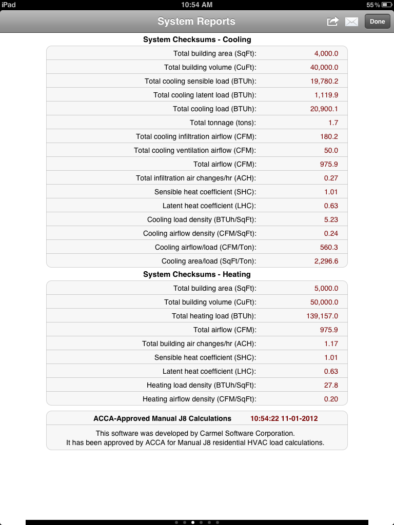
|

|
| Portrait Mode Screenshot of Page 3 of System Reports shows system checksums..... | ....Portrait Mode Screenshot of Page 4 of System Reports shows load breakdowns. |
e. It is possible to print or email your reports after you have viewed them on the screen. In the upper right hand corner of the System Reports page, you will see that there are a few buttons, as shown in the image below.
|
|
| Buttons to email, print, or finish your System Reports Views. |
Clicking on the first button, ![]() ,
will launch options to "air" print the current page being viewed or all pages in the Systems Reports. Choosing one or the other will then launch
a window prompting you to choose a printer.
,
will launch options to "air" print the current page being viewed or all pages in the Systems Reports. Choosing one or the other will then launch
a window prompting you to choose a printer.
|
|
| Choose an option before printing your reports.. |
Clicking on the second button, ![]() ,
will provide options to either email the current page being viewed or all pages in the Systems Reports. Choosing one or the other will then launch
a window where you can send an email from your predefined iPad email account. The report is automatically
attached as a PDF.
,
will provide options to either email the current page being viewed or all pages in the Systems Reports. Choosing one or the other will then launch
a window where you can send an email from your predefined iPad email account. The report is automatically
attached as a PDF.

|

|
| Choosing the option to email reports by pressing the email button... | ....launches your window to email the report to a client, a co-worker, or a boss. |
Option 2: Room Reports - When you click this button a new screen pops up which is a list of each of the rooms created in room-by-room mode, (if any). Below is a screenshot of a typical list.
|
|
| List of rooms created in Room by Room Input mode. |
When you tap your finger on a room name that you want to see, a one-page report pops up onto the screen. This is very similiar to the System Reports disccussed above. The total load, the total CFM, an AED curve, and the room load breakdown are all shown. See the image below for a typical screenshot of a room load report.
|
|
| Sample Room Report View. |
You can print the report or email it, similar to the System Reports described above. You can print or email all of the room reports at once by selecting the "All rooms" option in the list.
Option 3: Emailing Reports - Emailing a report is a little different than emailing System and Room reports individually. Instead of pie charts, this third option produces a detailed table which shows both the System and ALL room loads in a tabular layout. When this button is pressed, an email window is launched with the entire table embedded already in the email body, along with a .csv file that is a comma separated file that can be opened in Microsoft Excel or another spreadsheet tool. This can be directly mailed to your inbox back at work, a co worker, client, or boss.
|
|
| Sample Email Report |
Option 4: Email Database - This is a new option that allows you to export all of your ResLoad-J projects from one iPad device to another that is also running the ResLoad-J app. Often people use more than one device for home and work, and they want the ability to share the same project data between different devices. Another example is you may have a colleague at work who wants to look at your specific ResLoad-J project on their iPad. This Email Database option allows you to do all of the above. Once you select the option, it will open your email screen with the ResLoad-J project database attached to it. You can then send the email to any email address. Here are the steps that you should follow (they are also detailed in the Email Database email):
- Select the Email Database option to create the email
- Email the message to an email address that is accessible on the other device that is running the ResLoad-J app.
- On the receiving device, tap on the "resLoadJDB.sqlite" attachment within the email.
- A form will pop up on your iPad screen listing suggested apps to open the attachment with. Select the "Copy to HVAC ResLoad-J" app. This will copy the project database from the email over the one that is on the iPad. PLEASE NOTE THAT ALL OF THE PROJECTS ON THE RECEIVING DEVICE WILL BE PERMANENTLY OVER-WRITTEN.
- After step 4 above, the ResLoad-J app will open and display a message instructing you to close the app immediately and swipe it from memory. Then, re-open the app, and the new project database will appear.
|
|
| Sample Email Report |
Conclusion
This wraps up the online help for HVAC ResLoad-J iPad app. For more information, please refer to the following:
a. Click here for information about our periodic live training webinars.
b. Email us at [email protected] for any questions. To Top